Introduction
In this project we will be using the ESP32-CAM to create a Ring Door Bell type device. This small microcontroller has multiple capabilities, including:
- Camera Capability
- Wifi
- Bluetooth
- General Purpose Input Output (GPIO)
These features make it ideal for many applications, as it can interface with sensors and other hardware, and also communicate over Wifi or Bluetooth. During this project, we will be taking advantage of all of these features to create a Ring Door Bell device with this functionality:
- Detect motion
- Stream video
- Notify user
- Save images for later
- Have a web interface
- Have a case
Requesting Parts
If you would like to request the ESP32-CAM Microcontroller, please:
- Fill out the form here
-
Select kit option with ESP32-CAM
- If you have a base kit, you can receive just the ESP-32 CAM
- Donate here if you can!
Board Overview
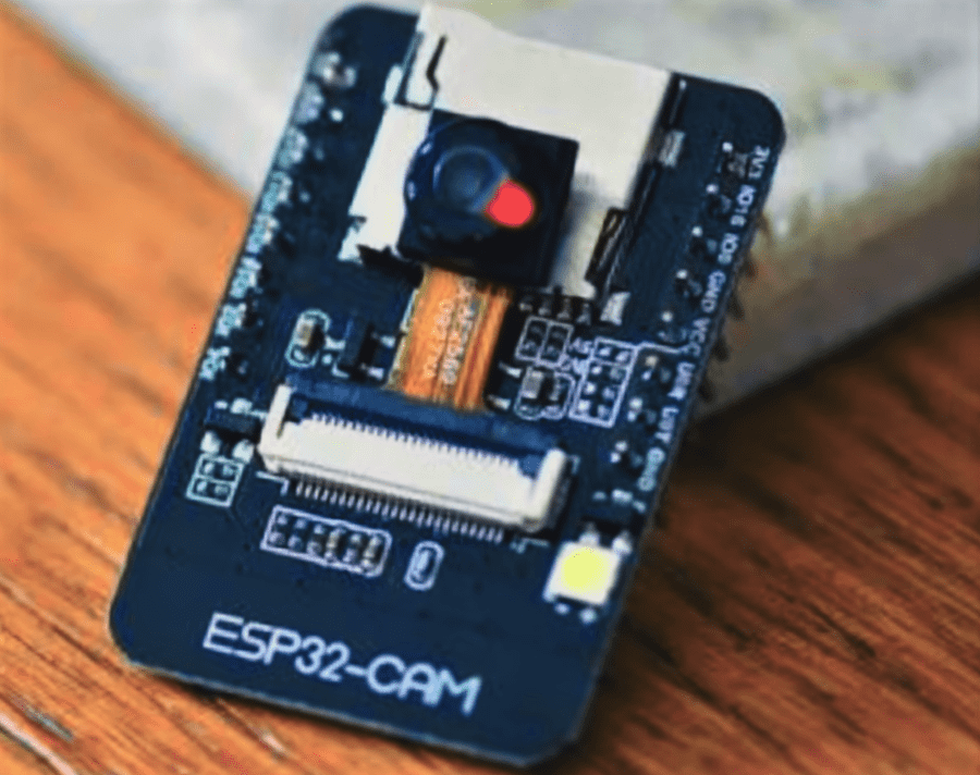
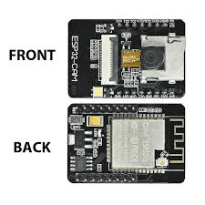
Looking at the front and back of the board, we can see multiple features. On the front of the board, we can see the camera at the center. This camera is connected to the board with a thin ribbon cable, so be careful with the microcontroller. Youre camera might have a piece of tape to protect the lens which you can remove. Underneath the camera is a metal square. This square is a microSD card slot that can be used to save images to or other data. On the bottom left, there is a white square. This is a small LED that can be used to illuminate the subject of the camera. It is very bright, so don’t look directly into it from a close distance.
On the backside of the board, you can see the main chip in the silver rectangle. The gold snake like path is an antenna band. If you need to, it is possible to extend the range of Wifi by connecting an antenna to the white circle on the bottom right side of the chip, as this is an antenna port. On the top left side of the board, look carefully for a button. It is directly to the left of the yellow square. This is the reset/program button. We will be using it to let the microcontroller know if it is in programming mode or not.
Programming the Board
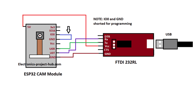
You may have noticed that the board does not have a USB port on it. To program it, we need a special device called an FTDI programmer. This device converts USB signals into a form of data the microcontroller can understand.
To connect the FTDI programmer, connect it to your microcontroller according to this wiring diagram using the parts in your kit. Pay attention to the arrow. This connects IO0 to GND. This wire is used to put the device into programming mode. I will be calling this “the jumper wire”
Next, download the Arduino IDE here and follow these tutorials to set it up depending on your system (Windows here, Mac/Linux here)
Then, select the ESP32-CAM Thinker Module and COM port through the Tools menu. Open the example code at “ File > Examples > ESP32 > Camera > Camera Web Server.” Change the SSID and password fields (leave the quotes in). Add ”//” in front of CAMERA_MODEL_WROVER_KIT and remove the ”//” in front of CAMERA_MODEL_AI_THINKER and save the file. To push the example code to the device, follow these instructions:
- Connect FTDI Programmer as shown previously
- Connect GND to IO0 (The jumper wire)
- Press reset button under board
- Push code from Arduino IDE
- Disconnect GND and IO0
- Press reset button under board
Now, open the serial monitor through the “Tools” menu and wait until a URL with an IP address appears. Make sure your computer is connected to the same network that you programmed the ESP32-CAM to connect to, and open the URL in your web browser. You can now start the camera stream and see the video displayed by your device. Try different resolutions and adjust the settings. There may be some issues with lag in the video depending on the quality of your network connection and other factors.
ESP32-CAM Code Explanation
Let’s run through the example code so you know how it works.
#include "esp_camera.h"
#include <WiFi.h>

//
// WARNING!!! Make sure that you have either selected ESP32 Wrover Module,
//            or another board which has PSRAM enabled
//

// Select camera model
//define CAMERA_MODEL_WROVER_KIT
//#define CAMERA_MODEL_ESP_EYE
//#define CAMERA_MODEL_M5STACK_PSRAM
//#define CAMERA_MODEL_M5STACK_WIDE
#define CAMERA_MODEL_AI_THINKER

#include "camera_pins.h"

const char* ssid = "****";
const char* password = "******";

void startCameraServer();
Lines 1-2 start by including files and libraries that the code needs to use. These store a bunch of code in the background so you have to do less work.
Lines 9-14 tell the compiler what type of board we’re using. In our club, we use the AI Thinker model, so we uncommented that line. The // comments out lines. It tells the compiler to ignore that line.
On the next few lines, we tell the microcontroller what our Wifi information is, and then start the Camera Server that runs on the ESP32-CAM.
void setup() {
  Serial.begin(115200);
  Serial.setDebugOutput(true);
  Serial.println();

  camera_config_t config;
  config.ledc_channel = LEDC_CHANNEL_0;
  config.ledc_timer = LEDC_TIMER_0;
  config.pin_d0 = Y2_GPIO_NUM;
  config.pin_d1 = Y3_GPIO_NUM;
  config.pin_d2 = Y4_GPIO_NUM;
  config.pin_d3 = Y5_GPIO_NUM;
  config.pin_d4 = Y6_GPIO_NUM;
  config.pin_d5 = Y7_GPIO_NUM;
  config.pin_d6 = Y8_GPIO_NUM;
  config.pin_d7 = Y9_GPIO_NUM;
  config.pin_xclk = XCLK_GPIO_NUM;
  config.pin_pclk = PCLK_GPIO_NUM;
  config.pin_vsync = VSYNC_GPIO_NUM;
  config.pin_href = HREF_GPIO_NUM;
  config.pin_sscb_sda = SIOD_GPIO_NUM;
  config.pin_sscb_scl = SIOC_GPIO_NUM;
  config.pin_pwdn = PWDN_GPIO_NUM;
  config.pin_reset = RESET_GPIO_NUM;
  config.xclk_freq_hz = 20000000;
  config.pixel_format = PIXFORMAT_JPEG;
On lines 2-4, we are setting up the serial monitor. This is the way the ESP talks to the Arduino IDE’s serial monitor. Serial is the name of the method used to communicate with the ESP and computer. 115200 is some information about the speed of the serial connection.
On lines 6-26, we’re letting the microcontroller know what ports to use to connect to the camera. This is so the microcontroller can read camera data. We also set up some camera format and speed options.
//init with high specs to pre-allocate larger buffers
  if(psramFound()){
    config.frame_size = FRAMESIZE_UXGA;
    config.jpeg_quality = 10;
    config.fb_count = 2;
  } else {
    config.frame_size = FRAMESIZE_SVGA;
    config.jpeg_quality = 12;
    config.fb_count = 1;
  }

#if defined(CAMERA_MODEL_ESP_EYE)
  pinMode(13, INPUT_PULLUP);
  pinMode(14, INPUT_PULLUP);
#endif
In this part, we set up some information about the camera size and streaming mode. On Lines 12-15, we check what type of microcontroller we’re using and set up a different mode. We can disregard this.
// camera init
  esp_err_t err = esp_camera_init(&config);
  if (err != ESP_OK) {
    Serial.printf("Camera init failed with error 0x%x", err);
    return;
  }

  sensor_t * s = esp_camera_sensor_get();
  //initial sensors are flipped vertically and colors are a bit saturated
  if (s->id.PID == OV3660_PID) {
    s->set_vflip(s, 1);//flip it back
    s->set_brightness(s, 1);//up the blightness just a bit
    s->set_saturation(s, -2);//lower the saturation
  }
  //drop down frame size for higher initial frame rate
  s->set_framesize(s, FRAMESIZE_QVGA);

#if defined(CAMERA_MODEL_M5STACK_WIDE)
  s->set_vflip(s, 1);
  s->set_hmirror(s, 1);
#endif
On lines 2-6, we make sure that we were able to start the camera successfully. We then adjust the image, as by default it is flipped and colors aren’t that great on lines 8 to 16. Finally, we check the camera type and modify the camera flip options if it we’re using a certain type of camera.
WiFi.begin(ssid, password);

  while (WiFi.status() != WL_CONNECTED) {
    delay(500);
    Serial.print(".");
  }
  Serial.println("");
  Serial.println("WiFi connected");

  startCameraServer();

  Serial.print("Camera Ready! Use 'http://");
  Serial.print(WiFi.localIP());
  Serial.println("' to connect");
}
Here, we’re almost ready. We connect to Wifi. Lines 3-8 just wait until we connect to wifi. Next, we start the camera server and print the IP Address information.
void loop() {
  // put your main code here, to run repeatedly:
  delay(10000);
}
In this final part of the code, we can add any code that we want to run.
Next Steps
In our next blog post, we will be working on receiving camera information with Python. We will also be working on some facial detection applications with python. As always, if you have any questions feel free to email cupertinoiot@gmail.com.


