What you will need:
- 5mm LEDs
- 220 Ohm Resistor
- 2 Jump Wires
- Node MCU/ESP8266
- A Breadboard
- Arduino IDE
- A ThingSpeak Account
Project Background
This tutorial will walk you through how to build your own RGB lights that can be controlled from the internet! Through this project, you will learn the basics of electronics, hardware, and software by setting up your own light module and writing code to interact with ThingSpeak to control your light.
Setting up the LED Module
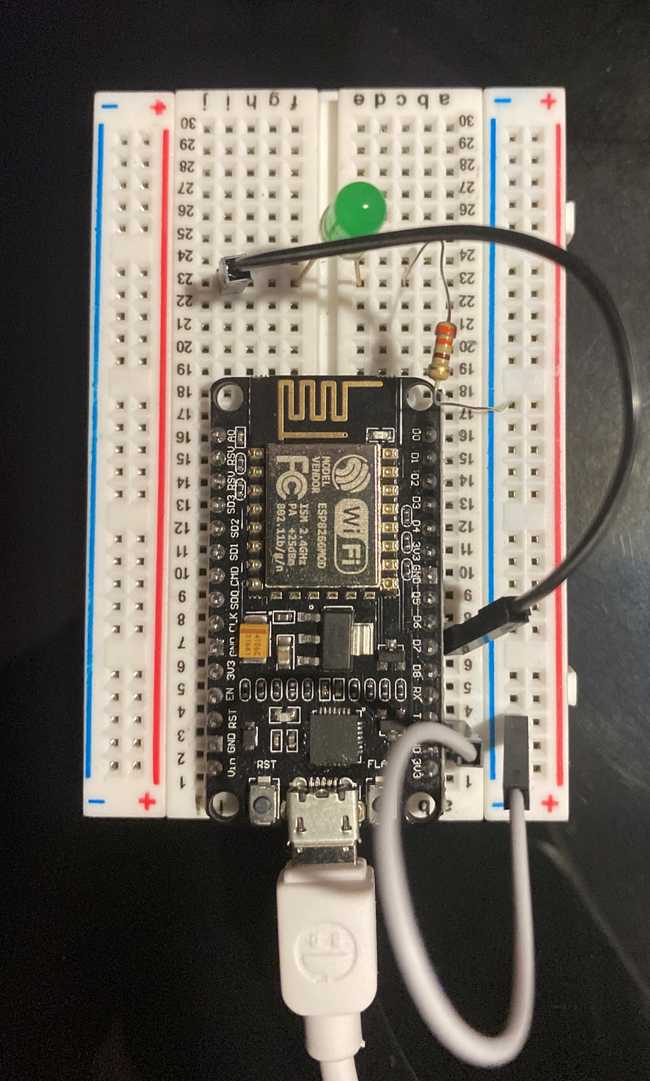
To set up the LED Module, we first place the NodeMCU on the breadboard by placing the port side of the Node facing outwards and firmly pressing the Node into the breadboard. Make sure the NodeMCU is completely inside the breadboard or else the module may not be powered properly.
Following this, add a jumper wire from the GND pin on the Node to the ”-” column on the breadboard. Following this, insert the longer side of the LED prong (Anode) into the same ”-” column where you placed the jump wire. Place the shorter side of the LED (Cathode) prong into another column in the breadboard.
Place a second jumper wire from the D7 pin on the Node to the same row as the shorter prong of the LED. Finally, place your resistor between both jump wires and the corresponding prong on the LED. The resistor is used to control the flow of current to LED.
Your board should look like this when you are done.
Connecting to ThingSpeak
Before you begin, make sure you create a ThingSpeak account first.
Steps:
-
Create a channel
- In the “My Channels” page click on “New Channel”
- Enter a name and brief description for your channel
- Enable Field 1 by checking the checkbox and provide a name (The field corresponds to the led on your module)
- Click “Save Channel”
-
Modify Channel Sharing Settings
- After creating your channel, go the “Sharing” tab and enable “Share Channel With Everyone”
-
Copy Channel ID
- Head to the “Channel Settings” tab and copy the “Channel ID” (you will need to input this ID in your code)
Once you have completed your steps, you are ready to move on! Check out our more detailed ESP ThingSpeak tutorial to learn more.
Controlling the LED
Open your Arduino IDE and ensure that you have the ESP8266 and ThingSpeak libraries installed.
In your file, add the code below. To connect to the internet you must first acquire your SSID and password of your wifi-router. In addition, paste the “Channel ID” you copied earlier into the “channel” variable.
#include "ThingSpeak.h"
#include <ESP8266WiFi.h>

// Replace your wifi credentials here
// ssid: your wifi name
// password: your wifi password
const char* ssid     = "YourWiFiName";
const char* password = "YourWiFiPassword";

// Replace with your own ThingSpeak Account Channel ID
unsigned long channel = 11111;

// 1 is a channel field. You don't need to change if you are following
// this tutorial. You can modify it according to your application
unsigned int led = 1;

WiFiClient  client;


void setup() {
  Serial.begin(115200);
  delay(100);

  pinMode(D7, OUTPUT);

  // We start by connecting to a WiFi network

  Serial.println();
  Serial.println();
  Serial.print("Connecting to ");
  Serial.println(ssid);

  WiFi.begin(ssid, password);

  while (WiFi.status() != WL_CONNECTED) {
    delay(500);
    Serial.print(".");
  }

  Serial.println("");
  Serial.println("WiFi connected");
  Serial.println("IP address: ");
  Serial.println(WiFi.localIP());
  Serial.print("Netmask: ");
  Serial.println(WiFi.subnetMask());
  Serial.print("Gateway: ");
  Serial.println(WiFi.gatewayIP());
  ThingSpeak.begin(client);

}

void loop() {

  // get the last data of the fields
  int led_1 = ThingSpeak.readFloatField(channel, led);

  if(led_1 == 0){
    digitalWrite(D7, 1);
    Serial.println("D1 is On..!");
  }
  else if(led_1 == 1){
    digitalWrite(D7, 0);
    Serial.println("D1 is Off..!");
  }

  Serial.println(led_1);
  delay(5000);
}
After this is complete, connect your NodeMCU with a micro-usb cable to your laptop and upload the code by pressing Cmd/Ctrl + U. While it is uploading, click on Tools > Serial Monitor to view log updates (such as connecting to Wifi and LED status).
Following this, head back to your ThingSpeak channel, click on “API Keys” tab and copy the “Write to Channel Feed” API link. Paste the link in the browser and you should be all set! From this page, in the edit the url periodically, changing the “field1=” attribute to between 0 and 1 (this is to toggle the LED on and off). As you do this, you should see your LED turning on and off (there will be a delay) as well as status updates in the Serial Monitor Log.
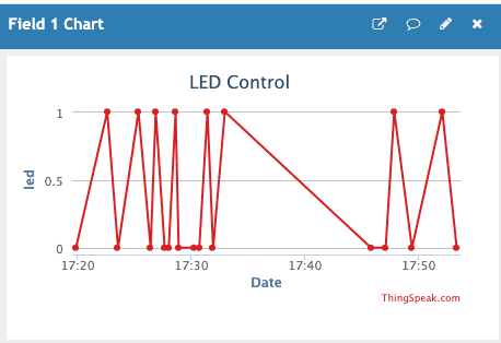
After a couple of changes to the “field1” value, you should see some data in your chart! The data represents the time the LED status changed and the status it was changed to.
Congratulations on creating your own LED light module and controlling it using ThingSpeak!
Challenge: Create a software UI that allows you to toggle the status of the LED switch using the ThingSpeak API. This can be as simple as creating an on/off button using html which makes a GET request to the ThingSpeak API or as complicated as you would like!
Send us a message on Slack if you need help and make sure to join.tinoiot.com to join our groups : )


